Scope:
This document provides instructions for proper spacing and alignment of multiple magnet track segments with even numbers of magnet pairs. Contact the factory for guidance in aligning tracks with odd numbers of magnet pairs or if tracks with even and odd magnet pairs are combined.
Background:
Airex linear motors are “ironless” in their construction, providing zero cogging forces as the forcer moves through the magnet track. Force ripple, however, is another form of force disturbance that comes from many sources, a primary being misalignment of magnets with respect to the electromagnetic field. This tech note addresses how to avoid unwanted force ripple from mis-alignment of magnet tracks.
Purpose:
Airex has three options in track lengths (P12, P15 and P20) with lengths of 24, 36 and 48 inches respectively. Many applications, however, require travel distances longer than the options stated above. Each magnet track segment is manufactured .010” shorter than its model number indicates (a 24” track is 23.99” in length), as needed to accommodate thermal expansion of each segment. Although long travel operating requirements can be met by merely placing magnet track segments “end to end”, avoiding force ripple mentioned earlier requires precise placement of each track relative to one another. Force ripple is reduced by maintaining an accurate magnet field pitch across the gap between track sections. To produce the required magnet track alignment, dowel pins can be accurately placed in the track mating surface such that they engage with the magnet track precision bores, producing the desired alignment.
Method:
Proper track assembly requires two steps. Step one is to maintain the correct magnet polarity track to track. Airex uses the track labels to designate proper orientation. Correct polarity is achieved when each magnet track is positioned with the track labels facing the same way (see Figure 1 below).
Step two is to maintain proper track to track spacing. Airex recommends using the dowel pin holes in each track segment. These holes are identified as the first hole on each track segment. Regarding the mounting surface, place dowel pins at a distance “X” (center to center). The dowel pins should not extend beyond 0.23” high for P20 and 0.10” high for P12 and P15 tracks. Refer to Figure 1.0 and Table 2.0 for pin diameter and “X” spacing distances.
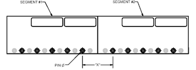
Figure 1.0: Alignment Reference Features.
| Model | Pin Æ in. [mm] | Pin Spacing “X” in. [mm] |
| P12 | 0.195 [4.95] | 2.400 [60.96] |
| P15 | 0.195 [4.95] | 2.400 [60.96] |
| P20 | 0.356 [9.04] | 2.400 [60.96] |
Table 2.0: Alignment Details.
Summary
Applications requiring multiple track lengths require an extra step to ensure smooth force delivery and avoid un-wanted force ripple. Force ripple is an electromagnetic/servo drive artifact that is influenced heavily by improper magnetic field spacing. The process described here addresses how proper field spacing is maintained when using more than one magnet track. For more information on this topic and other linear motor design, sizing or selection, please contact Airex directly.
Reference:
This information applies to standard magnet track assemblies. Please contact an Airex representative if dealing with a special model.